How a tube amplifier works, stage by stage
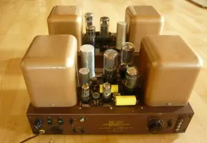
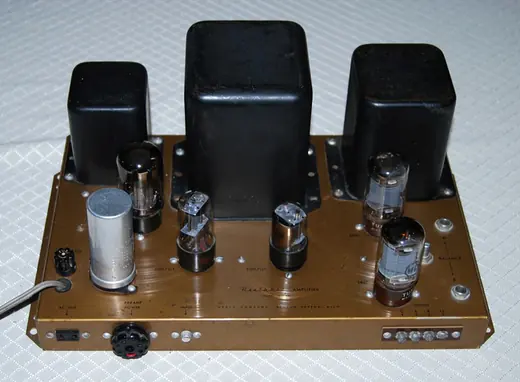
Pull the bottom plate off a 1950s mono amplifier and the first thing you notice is how few parts there are. A dozen resistors, a handful of capacitors, three or four tube sockets, two or three transformers the size of a fist. A modern receiver has more parts in its remote control. That sparseness is the reason these amplifiers are still repairable seventy years on, and it also means you can learn the whole signal path in an afternoon.
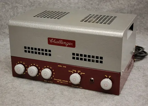
What follows is the path a signal takes through a typical push-pull power amplifier of the kind this archive is full of: a Bogen Challenger, an EICO HF-89, a Dynaco Stereo 70. Single-ended and preamp circuits differ in detail, but the logic is the same.
Stage one: the input tube
The signal arriving from a preamp or tuner is around one volt, sometimes less. The output tubes need tens of volts swinging on their grids before they deliver full power, so the first job is plain voltage gain.
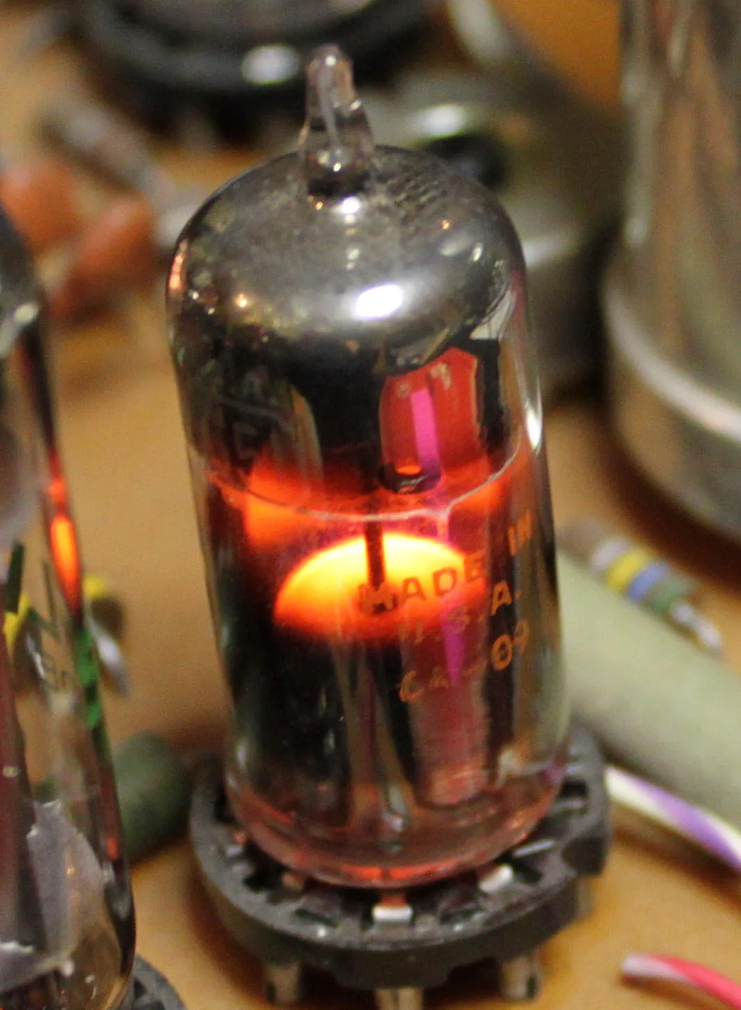
That job usually falls to one half of a small dual triode. The 12AX7 is the classic choice: RCA put it on sale in September 1947, and its amplification factor of about 100 means a small swing on the grid becomes a large swing at the plate. The 12AT7 and 12AU7 belong to the same family with much lower gain; designers picked whichever matched the drive the next stage needed.
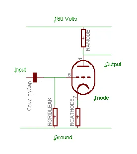
Inside the glass the principle is simple. A heated cathode boils off electrons. The plate, held at a couple of hundred volts positive through a resistor, attracts them. Between the two sits a fine wire mesh, the control grid. Make the grid a little more negative and fewer electrons get through; make it a little less negative and more do. Current through the plate resistor rises and falls with the grid, and that changing current becomes a changing voltage many times larger than the input.
The output of a triode stage is inverted. When the grid goes up, the plate goes down. Remember that, because the next stage depends on it.
Stage two: the phase splitter
A push-pull output stage has two tubes (or two pairs) that must be driven with mirror-image signals. While one grid swings positive, the other has to swing negative by the same amount. Something has to make that second, upside-down copy.
That something is the phase splitter, also called the phase inverter. In many 1950s circuits it is the other half of the same dual triode. The cathodyne (or "split-load") design takes one output from the plate and one from the cathode; the two are equal and opposite. The long-tailed pair uses both halves of a tube, with a shared cathode resistor, and gives more gain. Some early amplifiers used a centre-tapped interstage transformer instead, which needs no tube at all but costs more and limits the bandwidth.
On the bench, a weak or unbalanced phase splitter is a common reason a push-pull amplifier sounds thin or distorts early on one side. Replacing that single small tube fixes more "dead channel" complaints than any other part swap I know of.
Stage three: the output tubes
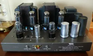
Now the signal is big enough to drive the power tubes. These are the tall bottles at the back of the chassis: 6L6, EL34, 6V6, EL84, KT88 and their relatives. Their job is not voltage gain but current. A loudspeaker has an impedance of a few ohms, and moving its cone takes amperes, not milliamperes.
A vacuum tube cannot deliver amperes into a few ohms directly. It is a high-voltage, low-current device. So the output tubes work into a much higher load, a few thousand ohms, and something has to convert that into the low-voltage, high-current drive a speaker wants.
How the output pair is biased decides the amplifier's class. In class A each tube conducts through the whole cycle; it runs hot and idles at full current whether music is playing or not. In class AB each tube carries more than half the waveform and rests partly when the other takes over, which gives far more power from the same pair. Most home amplifiers of the 1950s and 1960s ran their push-pull pairs in class AB1.
Bias itself comes in two styles. Cathode bias (or "self bias") puts a resistor under the cathodes so the tubes set their own operating point; it is forgiving and needs no adjustment. Fixed bias feeds a negative voltage to the grids from a separate supply; it squeezes out more power but needs setting with a meter, and a failed bias supply can cook a set of output tubes in minutes. Many restored amplifiers arrive with fresh tubes ruined because nobody checked the bias after replacing them.
Stage four: the output transformer
This is the heavy one, and the part that separates good amplifiers from ordinary ones. The output transformer matches the high impedance of the tubes to the low impedance of the speaker. Its primary winding connects to the tube plates; its secondary, with taps for 4, 8 and 16 ohms on most hi-fi models, connects to the speaker terminals.
In a push-pull design the primary has a centre tap fed by the high-voltage supply. Each tube pulls current through its own half. Because the DC currents flow in opposite directions, they cancel in the core, which lets the designer use a smaller transformer than a single-ended amplifier of the same power would need. The cancellation also removes even-order distortion produced by the tubes.
Bandwidth lives or dies here. A transformer with too little iron loses the bottom octave; one wound carelessly rings at high frequencies. That is why names like Acrosound, Partridge, Tango and Western Electric appear in the descriptions of the amplifiers in this archive. People were paying for the iron.
Many output transformers also carry an extra tap on each half of the primary for the screen grids. That is the ultra-linear connection, and it gets its own guide.
The loop back: negative feedback
Most amplifiers take a small slice of the signal from the speaker winding and feed it back to the input stage, out of phase. The amplifier then corrects its own errors: if the output is a little wrong, the difference shows up at the input and gets amplified in the opposite direction. Distortion drops, frequency response flattens, and the amplifier controls the speaker cone better.
The reference point for this approach is D.T.N. Williamson's design, published in Wireless World in April and May 1947: KT66 tubes connected as triodes in push-pull, a 20 dB feedback loop wrapped around all four stages and the output transformer, and no more than 0.1% distortion at 15 watts. Hundreds of thousands of builders copied it. Almost every commercial amplifier of the following decade borrowed something from it.
Feedback is not free. Around an output transformer it can make an amplifier unstable at very low or very high frequencies, and the Williamson itself was known for it. Builders who chase the sound of zero feedback usually end up with a single-ended triode instead. Williamson himself published a "New Version" of the circuit in August 1949, after readers wrote in about stability, so check which version a schematic follows before trusting its feedback values.
The part nobody photographs: the power supply
Every stage above needs high-voltage DC: 250 to 450 volts on the plates of a typical hi-fi amplifier, more on big transmitting-tube designs. The power transformer steps the mains up, a rectifier turns AC into pulsing DC, and a filter of capacitors and a choke or resistor smooths it.
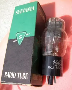
The rectifier is often a tube too: 5U4, 5AR4/GZ34, 5Y3, or the 5V4G in this archive. A tube rectifier warms up slowly, so the high voltage arrives gently. Some later amplifiers swapped in silicon diodes, which run cooler and give a stiffer supply.
The filter capacitors are where age shows first. Electrolytic capacitors dry out; after fifty or sixty years most of the originals are leaking, low in value or both. Hum, a buzzing note at twice the mains frequency, is the usual symptom. This is why the buying guide insists you never plug in an unknown amplifier straight from the wall.
Putting it together
Trace a signal through a Bogen or an EICO and you will find the same chain: a voltage stage, a phase splitter, a push-pull pair, an output transformer, a feedback resistor running back to the start, and a power supply feeding all of it. The differences between a $40 kit and a $400 flagship lie in the details. How big is the iron? Fixed bias or cathode bias? How much feedback, and how well is it tamed? How generous is the power supply?
Once you know the chain, a schematic stops looking like a wiring diagram and starts reading like a sentence. And a "dead" amplifier becomes a list of five places to look.
Short answers
Why does a tube amplifier need an output transformer when a transistor amplifier does not?
Tubes work at high voltage and low current, while a loudspeaker needs low voltage and high current into a few ohms. The output transformer converts one into the other. Transistor amplifiers can drive the speaker directly because transistors handle high currents at low voltage.
My amplifier hums even with the volume at zero. What is the usual cause?
On an amplifier that has not been restored, dried-out electrolytic filter capacitors in the power supply are the most common cause. The hum sits at twice the mains frequency. Have the capacitors replaced rather than running the amplifier for long in that state.
What is the difference between fixed bias and cathode bias?
Cathode bias uses a resistor under the output tubes so they set their own operating point and need no adjustment. Fixed bias feeds a negative voltage to the grids from a separate supply; it gives more power but must be set with a meter, especially after new output tubes are fitted.
Did every 1950s amplifier copy the Williamson circuit?
Not every one, but its use of push-pull output, heavy negative feedback and very low distortion set the benchmark. Later ultra-linear designs such as the Dynaco Stereo 70 kept the idea of global feedback while using fewer stages.
Checked against: Wikipedia: 12AX7 · Wikipedia: Push–pull output · Wikipedia: Williamson amplifier · Wikipedia: Ultra-linear